|
поискавой системы для электроныых деталей |
|
|
поискавой системы для электроныых деталей |
|
DB62 датащи(PDF) 1 Page - Cirrus Logic |
|
|
|||||||||||||||||||||||||||||
DB62 датащи(HTML) 1 Page - Cirrus Logic |
|
|
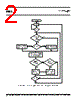
1 / 6 page  APEX MICROTECHNOLOGY CORPORATION • TELEPHONE (520) 690-8600 • FAX (520) 888-3329 • ORDERS (520) 690-8601 • EMAIL prodlit@apexmicrotech.com 1 M I C R O T E C H N O L O G Y DB62 Table 1. Commutation Table. The algorithm for the microcontroller is shown in figure 1. The program for Microchip® PIC 18F2331 is available for download on www.apexmicrotech.com. INTRODUCTION The DB62 is designed to demonstrate the capabilities of the SA305 as a 3 phase brushless DC motor driver IC. The PWM inputs to the SA305 are controlled by an on-board microcontroller. The EVAL49 board is pre-wired for all required and recommended external components. Please refer to ap- plications note 32 in the Apex catalog for guidance in filter component selection. The 1µF ceramic capacitors supplied with the kit are for high frequency bypassing of the VS and VDD supplies (C1, C11, C4 and C7 on the EVAL49 schematic). Two additional 100uF bypass capacitors are provided with the kit for the VS supplies (C2 and C12 on the EVAL49 schematic). Please refer to applications note 30 for help with power supply bypassing and other useful information. PWM CONTROL IN DB62 BLDC motors are electronically commutated based on the rotor position. The stator windings are energized in a sequence based upon the combination of three Hall sensor signals which provide the rotor position. In the DB62 the SA305 input PWM control is achieved by means of by an on-board Microchip® PIC 18F2331 microcontroller. The sequence table for com- mutation (obtained from the motor data sheet) is entered in Sensor Output Driver Output HALLA HALLB HALLC ØC (OUTC) ØB (OUTB) ØA (OUTA) CCW Rotation Facing Lead End 0 0 1 X HI LO 0 1 1 HI X LO 0 1 0 HI LO X 1 1 0 X LO HI 1 0 0 LO X HI 1 0 1 LO HI X CW Rotation Lead End 0 1 0 LO HI X 0 1 1 LO X HI 0 0 1 X LO HI 1 0 1 HI LO X 1 0 0 HI X LO 1 1 0 X HI LO the program memory of the microcontroller. Hall sensors A, B and C are connected to the IC pins of the Input Capture (IC) module in the PIC18F2331. This module interrupts on every transition on any of the IC pins. Upon interrupt, the interrupt service routine reads all the three inputs and loads the correct sequence for commutation. The following PWM control features are programmed in the MCU provided with the DB62: 1. User Controlled PWM frequency using external potentiom- eter (VFREQ in EVAL 49 board). The PWM frequency can be varied from 4 KHz to 118 KHz. 2. User Controlled PWM duty cycle using external potenti- ometer (VDUC in EVAL49 board). The voltage set by the potentiometer will act as a ‘Speed Reference’. The duty cycle can be varied from 0 % to 98 %. The Forward/Reverse button is provided to control the direction of the motor. Depending upon the direction, the cor- responding hall sensor commutation sequence is used and the PWM signals are generated accordingly. The START/STOP button can be used to run or stop the motor. As mentioned earlier, the MCU provided with the kit is pre- programmed for all of the features described above. The hall sensor commutation table that has been used in programming the MCU is shown in table 1. |
Аналогичный номер детали - DB62 |
|
Аналогичное описание - DB62 |
|
|
|
ссылки URL |
| Вашему бизинису помогли Аллдатащит? [ DONATE ] |
Что такое Аллдатащит | реклама | контакт | Конфиденциальность | Ссылка на техническое описание | обмен ссыками | поиск по производителю All Rights Reserved©Alldatasheet.com |
| Russian : Alldatasheetru.com | Korean : Alldatasheet.co.kr | Spanish : Alldatasheet.es | French : Alldatasheet.fr | Italian : Alldatasheetit.com Portuguese : Alldatasheetpt.com | Polish : Alldatasheet.pl | Vietnamese : Alldatasheet.vn Indian : Alldatasheet.in | Mexican : Alldatasheet.com.mx | British : Alldatasheet.co.uk | New Zealand : Alldatasheet.co.nz |
|
Family Site : ic2ic.com |
icmetro.com |
 Russian ▼
 English
 Chinese
 German
 Japanese
 Russian
 Korean
 Spanish
 French
 Italian
 Portuguese
 Polish
 Vietnamese
 Indian
 Mexican
 British
 New Zealand