|
поискавой системы для электроныых деталей |
|
|
поискавой системы для электроныых деталей |
|
LSP5523-R8A датащи(PDF) 3 Page - Diodes Incorporated |
|
|
|||||||||||||||||||||||||||||
LSP5523-R8A датащи(HTML) 3 Page - Diodes Incorporated |
|
|
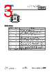
3 / 17 page  LSP5523 Document number: DS44073 Rev. 7 - 2 3 of 17 www.diodes.com May 2022 © 2022 Copyright Diodes Incorporated. All Rights Reserved. LSP5523 Pin Assignment 1 8 7 6 5 2 3 4 SS EN C O M P FB BS V IN SW G N D ( T O P V ie w ) E x p o s e d P a d o n B a c k s id e E S O P - 8 L Pin Descriptions Pin Name Name Pin Description 1 BS Bootstrap. This pin acts as the positive rail for the high- side switch’s gate driver. Connect a 0.01uF capacitor between BS and SW. 2 VIN Input Supply. Bypass this pin to GND with a low ESR capacitor. See Input Capacitor in the Application Information section. 3 SW Switch Output. Connect this pin to the switching end of the inductor. 4 GND Ground. 5 FB Feedback Input. The voltage at this pin is regulated to 0.925V. Connect to the resistor divider between output and ground to set output voltage. 6 COMP Compensation Pin. See Stability Compensation in the Application Information section. 7 EN Enable Input. When higher than 2.7V, this pin turns the IC on. When lower than 1.1V, this pin turns the IC off. Output voltage is discharged when the IC is off. This pin should not be left open. Recommend to put a 200K Ω pull-up resistor to Vin for startup. 8 SS Soft-Start Control Input. SS controls the soft-start period. Connect a capacitor from SS to GND to set the soft-start period. A 0.1uF capacitor sets the soft-start period to 13ms. To disable the soft-start feature, leave SS unconnected. — Exposed Pad Exposed Pad. Need to connect to GND pin. |
|
|
ссылки URL |
| Вашему бизинису помогли Аллдатащит? [ DONATE ] |
Что такое Аллдатащит | реклама | контакт | Конфиденциальность | Ссылка на техническое описание | обмен ссыками | поиск по производителю All Rights Reserved©Alldatasheet.com |
| Russian : Alldatasheetru.com | Korean : Alldatasheet.co.kr | Spanish : Alldatasheet.es | French : Alldatasheet.fr | Italian : Alldatasheetit.com Portuguese : Alldatasheetpt.com | Polish : Alldatasheet.pl | Vietnamese : Alldatasheet.vn Indian : Alldatasheet.in | Mexican : Alldatasheet.com.mx | British : Alldatasheet.co.uk | New Zealand : Alldatasheet.co.nz |
|
Family Site : ic2ic.com |
icmetro.com |
 Russian ▼
 English
 Chinese
 German
 Japanese
 Russian
 Korean
 Spanish
 French
 Italian
 Portuguese
 Polish
 Vietnamese
 Indian
 Mexican
 British
 New Zealand