|
поискавой системы для электроныых деталей |
|
|
поискавой системы для электроныых деталей |
|
ADE7756AN-REF датащи(PDF) 17 Page - Analog Devices |
|
|
|||||||||||||||||||||||||||||
ADE7756AN-REF датащи(HTML) 17 Page - Analog Devices |
|
|
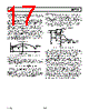
17 / 32 page  REV. 0 ADE7756 –17– Antialias Filter Figure 21 also shows an analog low-pass filter (RC) on the input to the modulator. This filter is present to prevent aliasing. Alias- ing is an artifact of all sampled systems. Figure 16 illustrates the effect, frequency components (arrows shown in black) above half the sampling frequency (also known as the Nyquist frequency, i.e., 447 kHz) is imaged or folded back down below 447 kHz (arrows shown in grey). This will happen with all ADCs no matter what the architecture is. In the example shown it can be seen that only frequencies near the sampling frequency, i.e., 894 kHz, will move into the band of interest for metering, i.e., 40 Hz–2 kHz. This fact will allow us to use a very simple LPF (Low-Pass Filter) to attenuate these high frequencies (near 900 kHz) and so prevent distortion in the band of interest. A simple RC filter (single-pole) with a corner frequency of 10 kHz will produce an attenuation of approxi- mately 40 dBs at 894 kHz—see Figure 15. This is sufficient to eliminate the effects of aliasing. FREQUENCY – kHz ALIASING EFFECTS 0 447 894 2 IMAGE FREQUENCIES SAMPLING FREQUENCY Figure 16. ADC and Signal Processing in Channel 1 ADC Transfer Function Below is an expression that relates the output of the LPF in the sigma-delta ADC to the analog input signal level. Both ADCs in the ADE7756 are designed to produce the same output code for the same input signal level. Code ADC V V IN REF () . , =× × 1 512 262 144 Therefore, with a full-scale signal on the input of 1 V, and an internal reference of 2.4 V, the ADC output code is nominally 165,151 or 2851Fh. The maximum code from the ADC is ±262,144, which is equivalent to an input signal level of ±1.6 V. However, for specified performance it is not recommended that the full-scale input signal level of ±1 V be exceeded. Reference Circuit Shown in Figure 17 is a simplified version of the reference output circuitry. The nominal reference voltage at the REFIN/OUT pin is 2.42 V. This is the reference voltage used for the ADCs in the ADE7756. However, Channel 1 has three input range selections that are selected by dividing down the reference value used for the ADC in Channel 1. The reference value used for Channel 1 is divided down to 1/2 and 1/4 of the nominal value by using an internal resistor divider as shown in Figure 17. 1.7k PTAT REFIN/OUT MAXIMUM LOAD = 10 A 2.42V 12.5k 12.5k 12.5k 12.5k REFERENCE INPUT TO ADC CHANNEL 1 (RANGE SELECT) 2.42V, 1.21V, 0.6V 2.5V OUTPUT IMPEDANCE 4k 60 A Figure 17. Reference Circuit Output The REFIN/OUT pin can be overdriven by an external source, e.g., an external 2.5 V reference. Note that the nominal refer- ence value supplied to the ADCs is now 2.5 V, not 2.42 V. This has the effect of increasing the nominal analog input signal range by 2.5/2.42 × 100% = 3%, or from 1 V to 1.03 V. The voltage of ADE7756 reference drifts slightly with temperature —see ADE7756 Specifications for the temperature coefficient specification (in ppm/ °C). The value of the temperature drift varies from part to part. On A-grade parts, the maximum temperature drift is not guaranteed. Since the reference is used for the ADCs in both Channel 1 and 2, any x% drift in the reference will result in 2x% deviation of the meter accuracy. The reference drift resulting from temperature changes is usually very small and it is typically much smaller than the drift of other components on a meter. However, if guaranteed temperature performance is needed, one needs to use an external voltage reference or to use B-grade parts. Alternatively, the meter can be calibrated at multiple temperatures. Real-time compensation can be easily achieved using the on the on-chip temperature sensor. |
|
ссылки URL |
| Вашему бизинису помогли Аллдатащит? [ DONATE ] |
Что такое Аллдатащит | реклама | контакт | Конфиденциальность | Ссылка на техническое описание | обмен ссыками | поиск по производителю All Rights Reserved©Alldatasheet.com |
| Russian : Alldatasheetru.com | Korean : Alldatasheet.co.kr | Spanish : Alldatasheet.es | French : Alldatasheet.fr | Italian : Alldatasheetit.com Portuguese : Alldatasheetpt.com | Polish : Alldatasheet.pl | Vietnamese : Alldatasheet.vn Indian : Alldatasheet.in | Mexican : Alldatasheet.com.mx | British : Alldatasheet.co.uk | New Zealand : Alldatasheet.co.nz |
|
Family Site : ic2ic.com |
icmetro.com |
 Russian ▼
 English
 Chinese
 German
 Japanese
 Russian
 Korean
 Spanish
 French
 Italian
 Portuguese
 Polish
 Vietnamese
 Indian
 Mexican
 British
 New Zealand