 |
поискавой системы для электроныых деталей |
|
|
поискавой системы для электроныых деталей |
|
The question interval is too short.
Please try again in a few seconds.

Hello, Please ask a question about IXYA15N65C3D1 Datasheet
# Example questions:
➢ How does transconductance change with increasing collector current (ic)?
➢ What is the approximate gate charge (qg) when the gate voltage is approximately 10v, given ic = 15a and ig = 10ma?
➢ Referring to figure 10, what is the approximate maximum collector current (ic) at a vce of 300v and a junction temperature of 50°c?
| Part No. | IXYA15N65C3D1 |
| Manufacturer | IXYS |
| Size | 220 Kbytes |
| Pages | 6 pages |
| Description | Preliminary Technical Information |


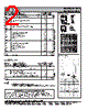


General Notes:
️· Data Sheets: These figures are typical of what you'd find in a MOSFET's data sheet.
️· Parameters: They show how the device behaves under various conditions, such as temperature, voltage, and current.
️· Abbreviations: Abbreviations are common in electronics documentation (e.g., "V" for Volt, "A" for Ampere, "ºC" for Celsius).
Figure Breakdown:
1. Transconductance
️· Description: This graph shows the relationship between the drain-source voltage (Vds) and the transconductance (gm) of the MOSFET. Transconductance is a measure of how much the output current changes with respect to a change in the gate-source voltage.
️· Key Information: Higher Vds results in a higher transconductance.
️· Axes: Vds (Vertical/Voltage) vs. gm (Horizontal/Transconductance)
2. Gate Charge
️· Description: This graph shows the gate charge (Qg) for different gate-source voltages (Vgs). Gate charge is the total charge required to be supplied to the gate to turn on the MOSFET.
️· Key Information: It details the gate charge components (Qgs, Qgd, Cies, Coes) and their values at various Vgs.
️· Axes: Qg (Vertical/NanoCoulombs) vs. Vgs (Horizontal/Voltage).
3. Maximum Transient Thermal Impedance
️· Description: Shows how the MOSFET's internal temperature rises over time when it dissipates power. Transient thermal impedance is a measure of how quickly heat can be removed from the device.
️· Key Information: A lower thermal impedance is better because it allows for more efficient heat removal, which helps prevent overheating and damage.
️· Axes: Pulse Width (Horizontal/Seconds) vs. Impedance (Vertical/Unitless).
4. Reverse-Bias Safe Operating Area
️· Description: This graph defines the limits within which the MOSFET can operate without risking damage under reverse bias conditions.
️· Key Information: It plots the maximum drain current (Ic) allowed at different drain-source voltages (Vds) while ensuring safe operation. The areas outlined represent safe operating zones.
️· Axes: Vds (Vertical/Voltage) vs. Ic (Horizontal/Amperes)
5. Capacitance
️· Description: This graph shows the capacitance of the MOSFET at different frequencies. Capacitance affects the switching speed of the MOSFET.
️· Key Information: Details different capacitance components like Cies, Coes.
️· Axes: C (Vertical/Farads) vs. f (Horizontal/Hz)
6. Transconductance
️· Description: Shows the relationship between drain-source voltage and transconductance.
️· Key Information: Details the value of gm for different Vds values.
️· Axes: Vds (Vertical/Voltage) vs. gm (Horizontal/Transconductance)
7. Gate Charge
️· Description: Details gate charge components.
️· Key Information: Shows Qgs, Qgd, Cies, and Coes against Vgs.
️· Axes: Qg (Vertical/NanoCoulombs) vs. Vgs (Horizontal/Voltage).
8. Maximum Transient Thermal Impedance
️· Description: Demonstrates the transient thermal impedance over time.
️· Key Information: Illustrates how quickly heat dissipates from the device
️· Axes: Pulse Width (Horizontal/Seconds) vs. Impedance (Vertical/Unitless).
9. Reverse-Bias Safe Operating Area
️· Description: Defines the reverse-bias safe operating area.
️· Key Information: Shows safe Ic vs Vds
️· Axes: Vds (Vertical/Voltage) vs. Ic (Horizontal/Amperes)
Important Notes:
️· Datasheet Consultation: This breakdown is meant to give you a general understanding. Always refer to the official data sheet for the most accurate and detailed information.
️· Context: The specific applications for these MOSFETs will influence how you interpret these parameters.
️· IXYS Corporation: This is the manufacturer of the MOSFETs.
General Notes:
️· Data Sheets: These figures are typical of what you'd find in a MOSFET's data sheet.
️· Parameters: They show how the device behaves under various conditions, such as temperature, voltage, and current.
️· Abbreviations: Abbreviations are common in electronics documentation (e.g., "V" for Volt, "A" for Ampere, "ºC" for Celsius).
Figure Breakdown:
1. Transconductance
️· Description: This graph shows the relationship between the drain-source voltage (Vds) and the transconductance (gm) of the MOSFET. Transconductance is a measure of how much the output current changes with respect to a change in the gate-source voltage.
️· Key Information: Higher Vds results in a higher transconductance.
️· Axes: Vds (Vertical/Voltage) vs. gm (Horizontal/Transconductance)
2. Gate Charge
️· Description: This graph shows the gate charge (Qg) for different gate-source voltages (Vgs). Gate charge is the total charge required to be supplied to the gate to turn on the MOSFET.
️· Key Information: It details the gate charge components (Qgs, Qgd, Cies, Coes) and their values at various Vgs.
️· Axes: Qg (Vertical/NanoCoulombs) vs. Vgs (Horizontal/Voltage).
3. Maximum Transient Thermal Impedance
️· Description: Shows how the MOSFET's internal temperature rises over time when it dissipates power. Transient thermal impedance is a measure of how quickly heat can be removed from the device.
️· Key Information: A lower thermal impedance is better because it allows for more efficient heat removal, which helps prevent overheating and damage.
️· Axes: Pulse Width (Horizontal/Seconds) vs. Impedance (Vertical/Unitless).
4. Reverse-Bias Safe Operating Area
️· Description: This graph defines the limits within which the MOSFET can operate without risking damage under reverse bias conditions.
️· Key Information: It plots the maximum drain current (Ic) allowed at different drain-source voltages (Vds) while ensuring safe operation. The areas outlined represent safe operating zones.
️· Axes: Vds (Vertical/Voltage) vs. Ic (Horizontal/Amperes)
5. Capacitance
️· Description: This graph shows the capacitance of the MOSFET at different frequencies. Capacitance affects the switching speed of the MOSFET.
️· Key Information: Details different capacitance components like Cies, Coes.
️· Axes: C (Vertical/Farads) vs. f (Horizontal/Hz)
6. Transconductance
️· Description: Shows the relationship between drain-source voltage and transconductance.
️· Key Information: Details the value of gm for different Vds values.
️· Axes: Vds (Vertical/Voltage) vs. gm (Horizontal/Transconductance)
7. Gate Charge
️· Description: Details gate charge components.
️· Key Information: Shows Qgs, Qgd, Cies, and Coes against Vgs.
️· Axes: Qg (Vertical/NanoCoulombs) vs. Vgs (Horizontal/Voltage).
8. Maximum Transient Thermal Impedance
️· Description: Demonstrates the transient thermal impedance over time.
️· Key Information: Illustrates how quickly heat dissipates from the device
️· Axes: Pulse Width (Horizontal/Seconds) vs. Impedance (Vertical/Unitless).
9. Reverse-Bias Safe Operating Area
️· Description: Defines the reverse-bias safe operating area.
️· Key Information: Shows safe Ic vs Vds
️· Axes: Vds (Vertical/Voltage) vs. Ic (Horizontal/Amperes)
Important Notes:
️· Datasheet Consultation: This breakdown is meant to give you a general understanding. Always refer to the official data sheet for the most accurate and detailed information.
️· Context: The specific applications for these MOSFETs will influence how you interpret these parameters.
️· IXYS Corporation: This is the manufacturer of the MOSFETs.
| Part No. | IXYA15N65C3D1 |
| Manufacturer | IXYS |
| Size | 220 Kbytes |
| Pages | 6 pages |
| Description | Preliminary Technical Information |
| Вашему бизинису помогли Аллдатащит? [ DONATE ] |
Что такое Аллдатащит | реклама | контакт | Конфиденциальность | Ссылка на техническое описание | обмен ссыками | поиск по производителю All Rights Reserved©Alldatasheet.com |
| Russian : Alldatasheetru.com | Korean : Alldatasheet.co.kr | Spanish : Alldatasheet.es | French : Alldatasheet.fr | Italian : Alldatasheetit.com Portuguese : Alldatasheetpt.com | Polish : Alldatasheet.pl | Vietnamese : Alldatasheet.vn Indian : Alldatasheet.in | Mexican : Alldatasheet.com.mx | British : Alldatasheet.co.uk | New Zealand : Alldatasheet.co.nz |
|
Family Site : ic2ic.com |
icmetro.com |
 Russian ▼
  English
 Chinese
 German
 Japanese
 Korean
 Spanish
 French
 Italian
 Portuguese
 Polish
 Vietnamese
 Indian
 Mexican
 British
 New Zealand