 |
поискавой системы для электроныых деталей |
|
|
поискавой системы для электроныых деталей |
|
The question interval is too short.
Please try again in a few seconds.

Hello, Please ask a question about LSP5523-R8A Datasheet
# Example questions:
➢ What is that condition, expressed in terms of cout, resr, fs, and a constant?
➢ What is the recommended rcomp value (in kω) for a 5v output with a 22uf ceramic capacitor?
➢ If you are designing a circuit with an input voltage of 12v and an output voltage of 8v, what inductor value (in uh) is suggested by the component selection guide (table 4)?
| Part No. | LSP5523-R8A |
| Manufacturer | DIODES |
| Size | 836 Kbytes |
| Pages | 17 pages |
| Description | 3A 27V Synchronous Buck Converter |

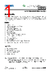






1. Overview & Features
️· Type: Synchronous Buck Regulator
️· Input Voltage Range: 4.5V - 28V (typical 5-23V)
️· Output Voltage: Adjustable, or fixed (typically 1.0V, 1.2V, 1.8V, 2.5V, 3.3V, 5V)
️· Output Current: Up to 3A
️· Synchronous Rectification: Uses internal MOSFETs for increased efficiency.
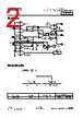
️· Adjustable Switching Frequency: (not explicitly stated but implied in figures)
️· Safety Features: Short Circuit Protection, Over Temperature Protection (OTP)
️· Package: ESOP-8L
2. Key Design Equations and Component Selection
️· Stability Compensation: *This is critical for proper operation.*
- C<sub>COMP1</sub> Calculation:
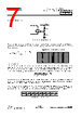
f<sub>Z1</sub> = 1/(4 * f<sub>crossover</sub>) is the condition for the zero frequency of the compensation capacitor.
C<sub>COMP1</sub> = 0.637 / (R<sub>COMP</sub> * f<sub>crossover</sub>) (Equation 10)
- C<sub>COMP2</sub> Calculation:
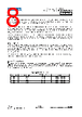
Used when the output capacitor ESR creates a zero frequency *below* 4 times the crossover frequency.
C<sub>COMP2</sub> = 1 / (π * C<sub>OUT</sub> * R<sub>ESR</sub> * f<sub>s</sub>) (Equation 11)
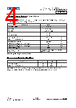
- Table 1 (Component Selection Guide): Provides recommended values for R<sub>COMP</sub>, C<sub>COMP1</sub>, C<sub>COMP2</sub>, and inductor for various output voltages and conditions. *This table is a good starting point for initial design.*
️· Inductor Selection: (Not explicitly detailed in equations, but is tied to stability and efficiency.) Consider factors like saturation current, DC resistance (DCR). The table provides suggestions.
️· Output Capacitor Selection: Key for stability and ripple. Low ESR capacitors are preferred. The table provides capacitor suggestions.
3. Stability Considerations – Critical Points
️· Crossover Frequency (f<sub>crossover</sub>): A key parameter for stability. The compensation components are designed to achieve a desired crossover frequency.
️· Zero Frequency (f<sub>Z1</sub>): The zero frequency of the compensation capacitor is important to control.
️· ESR (Equivalent Series Resistance): The ESR of the output capacitor significantly affects stability. High ESR requires a compensation capacitor (C<sub>COMP2</sub>).
4. Mechanical Information (ESOP-8L Package)
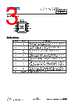
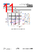
️· Detailed dimensions for the package are provided. Refer to the mechanical drawing for precise measurements.
5. Marking Information
️· Describes the information encoded on the package marking, including year, week, and output voltage indication.
6. Summary Tables (Key for Quick Reference)
️· Table 1 (Component Selection Guide): Provides recommended values for R<sub>COMP</sub>, C<sub>COMP1</sub>, C<sub>COMP2</sub>, and inductor based on input voltage range, output voltage, and other conditions.
Important Notes and Recommendations
️· Simulation: It's *highly* recommended to simulate the circuit using the regulator's SPICE model before building it. This will help optimize component values and verify stability.
️· Layout: PCB layout is critical. Pay attention to grounding, trace widths, and component placement to minimize parasitic effects and ensure stability. Keep the input and output capacitors close to the regulator.
️· Datasheet is Paramount: This summary is based on the provided text. *Always refer to the complete datasheet for detailed information, specifications, and application guidelines.*
1. Overview & Features
️· Type: Synchronous Buck Regulator
️· Input Voltage Range: 4.5V - 28V (typical 5-23V)
️· Output Voltage: Adjustable, or fixed (typically 1.0V, 1.2V, 1.8V, 2.5V, 3.3V, 5V)
️· Output Current: Up to 3A
️· Synchronous Rectification: Uses internal MOSFETs for increased efficiency.
️· Adjustable Switching Frequency: (not explicitly stated but implied in figures)
️· Safety Features: Short Circuit Protection, Over Temperature Protection (OTP)
️· Package: ESOP-8L
2. Key Design Equations and Component Selection
️· Stability Compensation: *This is critical for proper operation.*
- C<sub>COMP1</sub> Calculation:
f<sub>Z1</sub> = 1/(4 * f<sub>crossover</sub>) is the condition for the zero frequency of the compensation capacitor.
C<sub>COMP1</sub> = 0.637 / (R<sub>COMP</sub> * f<sub>crossover</sub>) (Equation 10)
- C<sub>COMP2</sub> Calculation:
Used when the output capacitor ESR creates a zero frequency *below* 4 times the crossover frequency.
C<sub>COMP2</sub> = 1 / (π * C<sub>OUT</sub> * R<sub>ESR</sub> * f<sub>s</sub>) (Equation 11)
- Table 1 (Component Selection Guide): Provides recommended values for R<sub>COMP</sub>, C<sub>COMP1</sub>, C<sub>COMP2</sub>, and inductor for various output voltages and conditions. *This table is a good starting point for initial design.*
️· Inductor Selection: (Not explicitly detailed in equations, but is tied to stability and efficiency.) Consider factors like saturation current, DC resistance (DCR). The table provides suggestions.
️· Output Capacitor Selection: Key for stability and ripple. Low ESR capacitors are preferred. The table provides capacitor suggestions.
3. Stability Considerations – Critical Points
️· Crossover Frequency (f<sub>crossover</sub>): A key parameter for stability. The compensation components are designed to achieve a desired crossover frequency.
️· Zero Frequency (f<sub>Z1</sub>): The zero frequency of the compensation capacitor is important to control.
️· ESR (Equivalent Series Resistance): The ESR of the output capacitor significantly affects stability. High ESR requires a compensation capacitor (C<sub>COMP2</sub>).
4. Mechanical Information (ESOP-8L Package)
️· Detailed dimensions for the package are provided. Refer to the mechanical drawing for precise measurements.
5. Marking Information
️· Describes the information encoded on the package marking, including year, week, and output voltage indication.
6. Summary Tables (Key for Quick Reference)
️· Table 1 (Component Selection Guide): Provides recommended values for R<sub>COMP</sub>, C<sub>COMP1</sub>, C<sub>COMP2</sub>, and inductor based on input voltage range, output voltage, and other conditions.
Important Notes and Recommendations
️· Simulation: It's *highly* recommended to simulate the circuit using the regulator's SPICE model before building it. This will help optimize component values and verify stability.
️· Layout: PCB layout is critical. Pay attention to grounding, trace widths, and component placement to minimize parasitic effects and ensure stability. Keep the input and output capacitors close to the regulator.
️· Datasheet is Paramount: This summary is based on the provided text. *Always refer to the complete datasheet for detailed information, specifications, and application guidelines.*
| Part No. | LSP5523-R8A |
| Manufacturer | DIODES |
| Size | 836 Kbytes |
| Pages | 17 pages |
| Description | 3A 27V Synchronous Buck Converter |
| Вашему бизинису помогли Аллдатащит? [ DONATE ] |
Что такое Аллдатащит | реклама | контакт | Конфиденциальность | Ссылка на техническое описание | обмен ссыками | поиск по производителю All Rights Reserved©Alldatasheet.com |
| Russian : Alldatasheetru.com | Korean : Alldatasheet.co.kr | Spanish : Alldatasheet.es | French : Alldatasheet.fr | Italian : Alldatasheetit.com Portuguese : Alldatasheetpt.com | Polish : Alldatasheet.pl | Vietnamese : Alldatasheet.vn Indian : Alldatasheet.in | Mexican : Alldatasheet.com.mx | British : Alldatasheet.co.uk | New Zealand : Alldatasheet.co.nz |
|
Family Site : ic2ic.com |
icmetro.com |
 Russian ▼
  English
 Chinese
 German
 Japanese
 Korean
 Spanish
 French
 Italian
 Portuguese
 Polish
 Vietnamese
 Indian
 Mexican
 British
 New Zealand