 |
поискавой системы для электроныых деталей |
|
|
поискавой системы для электроныых деталей |
|
The question interval is too short.
Please try again in a few seconds.

Hello, Please ask a question about AAT2510 Datasheet
# Example questions:
➢ How does the required input capacitor size (c in) change as the input voltage (v in) increases, and what factors influence this relationship?
➢ What is the primary function of the slope compensation feature in the aat2510 converter?
➢ The document highlights different slope compensation values based on output voltage. what is the slope compensation value for an aat2510 converter with a 5v output, and how does it compare to the value for a converter with a 0.6v output?
| Part No. | AAT2510 |
| Manufacturer | ANALOGICTECH |
| Size | 614 Kbytes |
| Pages | 20 pages |
| Description | Dual 400mA, 1MHz Step-Down DC-DC Converter |

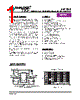




1. Overview
️· What it is: A constant frequency peak current mode PWM converter designed for step-down voltage conversion.
️· Function: Converts input voltage (2.7V - 5.5V) to an output voltage ranging from 0.6V up to the input voltage (adjustable).
️· Current Capability: 400mA load capability.
️· Efficiency: Up to 96% efficiency (typical). Light load efficiency is > 80% at 500µA.
️· Part Numbers: AAT2510 (fixed and adjustable versions)
2. Features
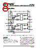
️· Independent Channels: Each channel has separate input, enable, feedback, and ground pins.
️· Switching Frequency: 1MHz.
️· Soft Start: Prevents output voltage overshoot and inrush current.
️· Enable Input: Low state forces converter into a low-power, non-switching state (<1µA bias current).
️· Low Dropout Operation: Operates even when input voltage is close to the output voltage. Duty cycle increases to 100% when input drops below output voltage.
️· Under-Voltage Lockout (UVLO): Ensures proper operation of internal circuitry.
️· Overload Protection: Peak inductor current is limited.
️· Thermal Protection: Disables switching when temperature is excessive (junction temperature threshold: 140°C with 15°C hysteresis).
3. Operation
️· Peak Current Mode Control: Uses peak current mode control with slope compensation to maintain stability.
️· Duty Cycle: From 50% up to 100%.
️· Slope Compensation: Important for stability (see Applications section).
️· Feedback: Includes an internal resistor divider (≥ 1.2V versions). For lower voltage versions, the feedback pin is tied directly to the error amplifier input.
️· 100% Duty Cycle: When input voltage drops below output voltage, converter enters 100% duty cycle.
4. Applications
️· Typical Applications: Portable devices, battery-powered systems, general power management.
️· Inductor Selection:
- Slope compensation requirement: For adjustable versions with 0.6V output, inductor is 4.7µH (internal slope compensation: 0.24A/µsec). For 2.5V output, inductor must be 10µH.
- Consider DCR (DC Resistance) losses when choosing an inductor.
️· Input Capacitor Selection:
- 4.7µF to 10µF ceramic capacitors (X7R or X5R) are recommended.
- The formula for input capacitor size depends on input voltage and required ripple level.
️· Table 1 Summary:
| Configuration | Output Voltage | Inductor | Slope Compensation |
|---|---|---|---|
| 0.6V Adjustable With External Resistive Divider | 0.6V to 2.0V | 4.7µH | 0.24A/µsec |
| 0.6V Adjustable With External Resistive Divider | 2.5V | 10µH | 0.24A/µsec |
| Fixed Output | 0.6V to 2.0V | 4.7µH | 0.24A/µsec |
| Fixed Output | 2.5V to 3.3V | 4.7µH | 0.48A/µsec |
1. Overview
️· What it is: A constant frequency peak current mode PWM converter designed for step-down voltage conversion.
️· Function: Converts input voltage (2.7V - 5.5V) to an output voltage ranging from 0.6V up to the input voltage (adjustable).
️· Current Capability: 400mA load capability.
️· Efficiency: Up to 96% efficiency (typical). Light load efficiency is > 80% at 500µA.
️· Part Numbers: AAT2510 (fixed and adjustable versions)
2. Features
️· Independent Channels: Each channel has separate input, enable, feedback, and ground pins.
️· Switching Frequency: 1MHz.
️· Soft Start: Prevents output voltage overshoot and inrush current.
️· Enable Input: Low state forces converter into a low-power, non-switching state (<1µA bias current).
️· Low Dropout Operation: Operates even when input voltage is close to the output voltage. Duty cycle increases to 100% when input drops below output voltage.
️· Under-Voltage Lockout (UVLO): Ensures proper operation of internal circuitry.
️· Overload Protection: Peak inductor current is limited.
️· Thermal Protection: Disables switching when temperature is excessive (junction temperature threshold: 140°C with 15°C hysteresis).
3. Operation
️· Peak Current Mode Control: Uses peak current mode control with slope compensation to maintain stability.
️· Duty Cycle: From 50% up to 100%.
️· Slope Compensation: Important for stability (see Applications section).
️· Feedback: Includes an internal resistor divider (≥ 1.2V versions). For lower voltage versions, the feedback pin is tied directly to the error amplifier input.
️· 100% Duty Cycle: When input voltage drops below output voltage, converter enters 100% duty cycle.
4. Applications
️· Typical Applications: Portable devices, battery-powered systems, general power management.
️· Inductor Selection:
- Slope compensation requirement: For adjustable versions with 0.6V output, inductor is 4.7µH (internal slope compensation: 0.24A/µsec). For 2.5V output, inductor must be 10µH.
- Consider DCR (DC Resistance) losses when choosing an inductor.
️· Input Capacitor Selection:
- 4.7µF to 10µF ceramic capacitors (X7R or X5R) are recommended.
- The formula for input capacitor size depends on input voltage and required ripple level.
️· Table 1 Summary:
| Configuration | Output Voltage | Inductor | Slope Compensation |
|---|---|---|---|
| 0.6V Adjustable With External Resistive Divider | 0.6V to 2.0V | 4.7µH | 0.24A/µsec |
| 0.6V Adjustable With External Resistive Divider | 2.5V | 10µH | 0.24A/µsec |
| Fixed Output | 0.6V to 2.0V | 4.7µH | 0.24A/µsec |
| Fixed Output | 2.5V to 3.3V | 4.7µH | 0.48A/µsec |
| Part No. | AAT2510 |
| Manufacturer | ANALOGICTECH |
| Size | 614 Kbytes |
| Pages | 20 pages |
| Description | Dual 400mA, 1MHz Step-Down DC-DC Converter |
| Вашему бизинису помогли Аллдатащит? [ DONATE ] |
Что такое Аллдатащит | реклама | контакт | Конфиденциальность | Ссылка на техническое описание | обмен ссыками | поиск по производителю All Rights Reserved©Alldatasheet.com |
| Russian : Alldatasheetru.com | Korean : Alldatasheet.co.kr | Spanish : Alldatasheet.es | French : Alldatasheet.fr | Italian : Alldatasheetit.com Portuguese : Alldatasheetpt.com | Polish : Alldatasheet.pl | Vietnamese : Alldatasheet.vn Indian : Alldatasheet.in | Mexican : Alldatasheet.com.mx | British : Alldatasheet.co.uk | New Zealand : Alldatasheet.co.nz |
|
Family Site : ic2ic.com |
icmetro.com |
 Russian ▼
  English
 Chinese
 German
 Japanese
 Korean
 Spanish
 French
 Italian
 Portuguese
 Polish
 Vietnamese
 Indian
 Mexican
 British
 New Zealand