|
поискавой системы для электроныых деталей |
|
|
поискавой системы для электроныых деталей |
|
TMP86FS49AIUG датащи(PDF) 260 Page - Toshiba Semiconductor |
|
|
|||||||||||||||||||||||||||||
TMP86FS49AIUG датащи(HTML) 260 Page - Toshiba Semiconductor |
|
|
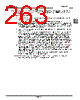
260 / 296 page  Page 244 20. Serial PROM Mode 20.6 Operation Mode TMP86FS49AIUG Description of the flash memory writing mode 1. The 1st byte of the received data contains the matching data. When the serial PROM mode is acti- vated, TMP86FS49AIUG (hereafter called device), waits to receive the matching data (5AH). Upon reception of the matching data, the device automatically adjusts the UART’s initial baud rate to 9600 bps. 2. When receiving the matching data (5AH), the device transmits an echo back data (5AH) as the second byte data to the external controller. If the device can not recognize the matching data, it does not transmit the echo back data and waits for the matching data again with automatic baud rate adjust- ment. Therefore, the external controller should transmit the matching data repeatedly till the device transmits an echo back data. The transmission repetition count varies depending on the frequency of device. For details, refer to Table 20-5. 3. The 3rd byte of the received data contains the baud rate modification data. The five types of baud rate modification data shown in Table 20-4 are available. Even if baud rate is not modified, the external controller should transmit the initial baud rate data (28H: 9600 bps). 4. Only when the 3rd byte of the received data contains the baud rate modification data corresponding to the device's operating frequency, the device echoes back data the value which is the same data in the 4th byte position of the received data. After the echo back data is transmitted, baud rate modification becomes effective. If the 3rd byte of the received data does not contain the baud rate modification data, the device enters the halts condition after sending 3 bytes of baud rate modification error code (62H). 5. The 5th byte of the received data contains the command data (30H) to write the flash memory. 6. When the 5th byte of the received data contains the operation command data shown in Table 1-6, the device echoes back the value which is the same data in the 6th byte position of the received data (in this case, 30H). If the 5th byte of the received data does not contain the operation command data, the device enters the halt condition after sending 3 bytes of the operation command error code (63H). 7. The 7th byte contains the data for 15 to 8 bits of the password count storage address. When the data received with the 7th byte has no receiving error, the device does not send any data. If a receiving error or password error occurs, the device does not send any data and enters the halt condition. 8. The 9th byte contains the data for 7 to 0 bits of the password count storage address. When the data received with the 9th byte has no receiving error, the device does not send any data. If a receiving error or password error occurs, the device does not send any data and enters the halt condition. 9. The 11th byte contains the data for 15 to 8 bits of the password comparison start address. When the data received with the 11th byte has no receiving error, the device does not send any data. If a receiv- ing error or password error occurs, the device does not send any data and enters the halt condition. 10. The 13th byte contains the data for 7 to 0 bits of the password comparison start address. When the data received with the 13th byte has no receiving error, the device does not send any data. If a receiv- ing error or password error occurs, the device does not send any data and enters the halt condition. 11. The 15th through m’th bytes contain the password data. The number of passwords becomes the data (N) stored in the password count storage address. The external password data is compared with N- byte data from the address specified by the password comparison start address. The external control- ler should send N-byte password data to the device. If the passwords do not match, the device enters the halt condition without returning an error code to the external controller. If the addresses from FFE0H to FFFFH are filled with “FFH”, the passwords are not conpared because the device is consid- ered as a blank product. 12. The m’th + 1 through n’th - 2 bytes of the received data contain the binary data in the Intel Hex for- mat. No received data is echoed back to the external controller. After receiving the start mark (3AH for “:”) in the Intel Hex format, the device starts data record reception. Therefore, the received data except 3AH is ignored until the start mark is received. After receiving the start mark, the device receives the data record, that consists of data length, address, record type, write data and checksum. Since the device starts checksum calculation after receiving an end record, the external controller should wait for the checksum after sending the end record. If a receiving error or Intel Hex format error occurs, the device enters the halts condition without returning an error code to the external con- troller. 13. The n’th - 1 and n’th bytes contain the checksum upper and lower bytes. For details on how to calcu- late the SUM, refer to " 20.8 Checksum (SUM) ". The checksum is calculated only when the end record is detected and no receiving error or Intel Hex format error occurs. After sending the end |
|
ссылки URL |
| Вашему бизинису помогли Аллдатащит? [ DONATE ] |
Что такое Аллдатащит | реклама | контакт | Конфиденциальность | Ссылка на техническое описание | обмен ссыками | поиск по производителю All Rights Reserved©Alldatasheet.com |
| Russian : Alldatasheetru.com | Korean : Alldatasheet.co.kr | Spanish : Alldatasheet.es | French : Alldatasheet.fr | Italian : Alldatasheetit.com Portuguese : Alldatasheetpt.com | Polish : Alldatasheet.pl | Vietnamese : Alldatasheet.vn Indian : Alldatasheet.in | Mexican : Alldatasheet.com.mx | British : Alldatasheet.co.uk | New Zealand : Alldatasheet.co.nz |
|
Family Site : ic2ic.com |
icmetro.com |
 Russian ▼
 English
 Chinese
 German
 Japanese
 Russian
 Korean
 Spanish
 French
 Italian
 Portuguese
 Polish
 Vietnamese
 Indian
 Mexican
 British
 New Zealand