 |
поискавой системы для электроныых деталей |
|
|
поискавой системы для электроныых деталей |
|
The question interval is too short.
Please try again in a few seconds.

Hello, Please ask a question about LT1161 Datasheet
# Example questions:
➢ Several schematics include components labeled '0.1µf' and '5.1k'. what role do these components likely play in the circuit's overall performance?
➢ What appears to be the primary function of the lt1161 in these circuits?
➢ The diagrams depict multiple mosfets (e.g., mtp36n06e, rfd16n05). what is a common function of mosfets in these types of circuits and what might they be switching?
| Part No. | LT1161 |
| Manufacturer | LINER |
| Size | 196 Kbytes |
| Pages | 12 pages |
| Description | Quad Protected High-Side MOSFET Driver |


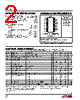
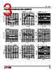
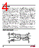

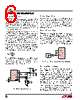


1. Core Component:
️· LT1161: This is the central IC. It's a synchronous buck regulator, meaning it efficiently converts a higher voltage to a lower voltage (downconversion). This is evidenced by the repeated mention of it in the documents.
2. Circuit Function & Topology (Based on Visuals & Data):
️· Buck Regulator: As mentioned before, the core function is voltage reduction. The schematics and tables suggest a robust design for this purpose.
️· Synchronous Rectification: The term "synchronous" indicates the use of MOSFETs to switch the output voltage in place of traditional diodes, improving efficiency.
️· PWM (Pulse Width Modulation): The regulator uses PWM to control the output voltage.
️· Feedback Loop: The presence of resistors and capacitors (likely forming a feedback network) indicate a feedback loop for maintaining stable output voltage.
3. Key Components & Their Roles (From Tables & Schematics - Best Guess):
️· MOSFETs (e.g., MTP36N06E, RFD16N05): These are crucial for switching. The data sheets for these (and any others used) would be vital to understanding the design.
️· Capacitors (various values, often 1µF, 0.1µF): Used for filtering, decoupling, and within the feedback loop.
️· Resistors (various values, e.g., 5.1k, 2k): Used for current limiting, voltage division, and feedback loop components.
️· Inductor: (Not explicitly mentioned but implied by the regulator topology) - It's a crucial element in a buck regulator for energy storage.
️· Diodes (e.g., 1N4744): Used for protection and possibly in the rectifier stage.
4. Table Data Interpretation:
️· The tables appear to describe configuration and parameter settings for different circuit iterations or variations. Each column likely represents a different circuit or test setup.
️· The values for components (resistors, capacitors, inductor current) are important for tuning and optimizing the regulator's performance.
️· The "Load" values in several tables are crucial to understanding performance under load.
️· The column labels like "18", "16", "14" are almost certainly referring to pin numbers on the LT1161 IC and other components. Knowing the pinout diagram of the LT1161 is *critical* to interpreting these labels.
5. Notes & Information (From the very end of the documents):
️· Linear Technology Corporation: This is the manufacturer of the LT1161.
️· Disclaimer: The legal disclaimer reinforces the "use at your own risk" nature of the document.
Areas Requiring More Context (CRITICAL for Full Understanding):
️· LT1161 Pinout Diagram: *Absolutely essential.* The numbers in the tables refer to pins; without a pinout, those numbers are meaningless.
️· Schematic Diagrams: I don't see the complete schematic diagrams, only snippets and references. Having the full schematics would allow for a detailed analysis.
️· Purpose of the Circuit: What is this regulator powering? Knowing the load (e.g., a microcontroller, motor, LEDs) is vital.
️· Input Voltage Range: What is the range of input voltage to the regulator?
️· Output Voltage: What is the target output voltage?
️· Datasheets: The datasheets for *all* the components (LT1161, MOSFETs, capacitors, resistors, inductor, diodes) are absolutely necessary for understanding their specific parameters and limitations.
️· Design Goals: What were the design constraints? (Efficiency, size, cost, etc.)
In summary, this is a design document for a switching regulator based on the Linear Technology LT1161. It's a complex design involving synchronous rectification and PWM control. A complete understanding would require significantly more context, specifically the LT1161 pinout and complete schematic diagrams, along with datasheets for the used components.
1. Core Component:
️· LT1161: This is the central IC. It's a synchronous buck regulator, meaning it efficiently converts a higher voltage to a lower voltage (downconversion). This is evidenced by the repeated mention of it in the documents.
2. Circuit Function & Topology (Based on Visuals & Data):
️· Buck Regulator: As mentioned before, the core function is voltage reduction. The schematics and tables suggest a robust design for this purpose.
️· Synchronous Rectification: The term "synchronous" indicates the use of MOSFETs to switch the output voltage in place of traditional diodes, improving efficiency.
️· PWM (Pulse Width Modulation): The regulator uses PWM to control the output voltage.
️· Feedback Loop: The presence of resistors and capacitors (likely forming a feedback network) indicate a feedback loop for maintaining stable output voltage.
3. Key Components & Their Roles (From Tables & Schematics - Best Guess):
️· MOSFETs (e.g., MTP36N06E, RFD16N05): These are crucial for switching. The data sheets for these (and any others used) would be vital to understanding the design.
️· Capacitors (various values, often 1µF, 0.1µF): Used for filtering, decoupling, and within the feedback loop.
️· Resistors (various values, e.g., 5.1k, 2k): Used for current limiting, voltage division, and feedback loop components.
️· Inductor: (Not explicitly mentioned but implied by the regulator topology) - It's a crucial element in a buck regulator for energy storage.
️· Diodes (e.g., 1N4744): Used for protection and possibly in the rectifier stage.
4. Table Data Interpretation:
️· The tables appear to describe configuration and parameter settings for different circuit iterations or variations. Each column likely represents a different circuit or test setup.
️· The values for components (resistors, capacitors, inductor current) are important for tuning and optimizing the regulator's performance.
️· The "Load" values in several tables are crucial to understanding performance under load.
️· The column labels like "18", "16", "14" are almost certainly referring to pin numbers on the LT1161 IC and other components. Knowing the pinout diagram of the LT1161 is *critical* to interpreting these labels.
5. Notes & Information (From the very end of the documents):
️· Linear Technology Corporation: This is the manufacturer of the LT1161.
️· Disclaimer: The legal disclaimer reinforces the "use at your own risk" nature of the document.
Areas Requiring More Context (CRITICAL for Full Understanding):
️· LT1161 Pinout Diagram: *Absolutely essential.* The numbers in the tables refer to pins; without a pinout, those numbers are meaningless.
️· Schematic Diagrams: I don't see the complete schematic diagrams, only snippets and references. Having the full schematics would allow for a detailed analysis.
️· Purpose of the Circuit: What is this regulator powering? Knowing the load (e.g., a microcontroller, motor, LEDs) is vital.
️· Input Voltage Range: What is the range of input voltage to the regulator?
️· Output Voltage: What is the target output voltage?
️· Datasheets: The datasheets for *all* the components (LT1161, MOSFETs, capacitors, resistors, inductor, diodes) are absolutely necessary for understanding their specific parameters and limitations.
️· Design Goals: What were the design constraints? (Efficiency, size, cost, etc.)
In summary, this is a design document for a switching regulator based on the Linear Technology LT1161. It's a complex design involving synchronous rectification and PWM control. A complete understanding would require significantly more context, specifically the LT1161 pinout and complete schematic diagrams, along with datasheets for the used components.
| Part No. | LT1161 |
| Manufacturer | LINER |
| Size | 196 Kbytes |
| Pages | 12 pages |
| Description | Quad Protected High-Side MOSFET Driver |
| Вашему бизинису помогли Аллдатащит? [ DONATE ] |
Что такое Аллдатащит | реклама | контакт | Конфиденциальность | Ссылка на техническое описание | обмен ссыками | поиск по производителю All Rights Reserved©Alldatasheet.com |
| Russian : Alldatasheetru.com | Korean : Alldatasheet.co.kr | Spanish : Alldatasheet.es | French : Alldatasheet.fr | Italian : Alldatasheetit.com Portuguese : Alldatasheetpt.com | Polish : Alldatasheet.pl | Vietnamese : Alldatasheet.vn Indian : Alldatasheet.in | Mexican : Alldatasheet.com.mx | British : Alldatasheet.co.uk | New Zealand : Alldatasheet.co.nz |
|
Family Site : ic2ic.com |
icmetro.com |
 Russian ▼
  English
 Chinese
 German
 Japanese
 Korean
 Spanish
 French
 Italian
 Portuguese
 Polish
 Vietnamese
 Indian
 Mexican
 British
 New Zealand