 |
поискавой системы для электроныых деталей |
|
|
поискавой системы для электроныых деталей |
|
The question interval is too short.
Please try again in a few seconds.

Hello, Please ask a question about 93LC46-I/P Datasheet
# Example questions:
➢ What must happen *before* any erase or write instruction can be executed?
➢ What is the key difference between the erase and eral instructions?
➢ What causes this conflict, and how can it be avoided?
| Part No. | 93LC46-I/P |
| Manufacturer | MICROCHIP |
| Size | 321 Kbytes |
| Pages | 20 pages |
| Description | 1K/2K/4K 2.5V Microwire Serial EEPROM |


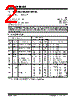
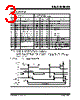
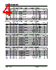


1. Organization and Addressing:
️· Organization: Available in both (x16) and (x8) organizations.
- (x16) = 16 bits per memory location
- (x8) = 8 bits per memory location
️· ORG Pin: Determines the organization:
- Connected to VCC: (x16) organization
- Connected to Ground: (x8) organization
️· Memory Size: (This isn't explicitly stated, but you would need to refer to the full datasheet for the specific memory sizes available.)
2. Operation & Commands:
️· Start Condition: Detected when CS and DI are high simultaneously on a rising edge of CLK.
️· EWDS (Erase/Write Disable):
- Default power-up state.
- All programming modes are disabled.
- Allows normal read operation.
️· EWEN (Erase/Write Enable):
- Must be executed before ERASE or WRITE operations.
️· ERAL (Erase All):
- Erases the entire memory array to all logical '1's.
- Takes 8ms typical
- Command is ensured at 5V ±10%
️· ERASE:
- Erases a single memory location to all logical '1's.
- Takes 4ms per word typical.
️· WRITE:
- Writes data to a single memory location.
- Takes 4ms per word typical.
️· WRAL (Write All):
- Writes data to the entire memory array
- Includes an automatic ERAL
- Requires the chip to be in the EWEN status.
- Takes 16ms typical.
️· Ready/Busy Indicator: The DO pin indicates the status during programming:
- DO Low = Programming in progress
- DO High = Programming complete and device ready
3. Timing & Electrical Characteristics (Important Notes):
️· VCC Levels: Programming operations (ERASE, WRITE, ERASE ALL, WRITE ALL) require VCC above 1.4V.
️· CS Timing: CS must be low before the last bit of data during a programming cycle to initiate it.
️· "Dummy Zero": A dummy zero bit precedes read operations.
️· Data Protection: Data protection circuitry inhibits programming when VCC falls below 1.4V.
️· Read Timing: Stable data output (T PD) is specified in the full datasheet.
4. Important Considerations:
️· Refer to Full Datasheet: This is just an excerpt. For complete specifications (memory sizes, pin configurations, electrical characteristics, timing diagrams), refer to the full datasheet.
️· Bus Conflicts: Be cautious about connecting DI and DO together, as bus conflicts can occur during the "dummy zero" state.
1. Organization and Addressing:
️· Organization: Available in both (x16) and (x8) organizations.
- (x16) = 16 bits per memory location
- (x8) = 8 bits per memory location
️· ORG Pin: Determines the organization:
- Connected to VCC: (x16) organization
- Connected to Ground: (x8) organization
️· Memory Size: (This isn't explicitly stated, but you would need to refer to the full datasheet for the specific memory sizes available.)
2. Operation & Commands:
️· Start Condition: Detected when CS and DI are high simultaneously on a rising edge of CLK.
️· EWDS (Erase/Write Disable):
- Default power-up state.
- All programming modes are disabled.
- Allows normal read operation.
️· EWEN (Erase/Write Enable):
- Must be executed before ERASE or WRITE operations.
️· ERAL (Erase All):
- Erases the entire memory array to all logical '1's.
- Takes 8ms typical
- Command is ensured at 5V ±10%
️· ERASE:
- Erases a single memory location to all logical '1's.
- Takes 4ms per word typical.
️· WRITE:
- Writes data to a single memory location.
- Takes 4ms per word typical.
️· WRAL (Write All):
- Writes data to the entire memory array
- Includes an automatic ERAL
- Requires the chip to be in the EWEN status.
- Takes 16ms typical.
️· Ready/Busy Indicator: The DO pin indicates the status during programming:
- DO Low = Programming in progress
- DO High = Programming complete and device ready
3. Timing & Electrical Characteristics (Important Notes):
️· VCC Levels: Programming operations (ERASE, WRITE, ERASE ALL, WRITE ALL) require VCC above 1.4V.
️· CS Timing: CS must be low before the last bit of data during a programming cycle to initiate it.
️· "Dummy Zero": A dummy zero bit precedes read operations.
️· Data Protection: Data protection circuitry inhibits programming when VCC falls below 1.4V.
️· Read Timing: Stable data output (T PD) is specified in the full datasheet.
4. Important Considerations:
️· Refer to Full Datasheet: This is just an excerpt. For complete specifications (memory sizes, pin configurations, electrical characteristics, timing diagrams), refer to the full datasheet.
️· Bus Conflicts: Be cautious about connecting DI and DO together, as bus conflicts can occur during the "dummy zero" state.
| Part No. | 93LC46-I/P |
| Manufacturer | MICROCHIP |
| Size | 321 Kbytes |
| Pages | 20 pages |
| Description | 1K/2K/4K 2.5V Microwire Serial EEPROM |
| Вашему бизинису помогли Аллдатащит? [ DONATE ] |
Что такое Аллдатащит | реклама | контакт | Конфиденциальность | Ссылка на техническое описание | обмен ссыками | поиск по производителю All Rights Reserved©Alldatasheet.com |
| Russian : Alldatasheetru.com | Korean : Alldatasheet.co.kr | Spanish : Alldatasheet.es | French : Alldatasheet.fr | Italian : Alldatasheetit.com Portuguese : Alldatasheetpt.com | Polish : Alldatasheet.pl | Vietnamese : Alldatasheet.vn Indian : Alldatasheet.in | Mexican : Alldatasheet.com.mx | British : Alldatasheet.co.uk | New Zealand : Alldatasheet.co.nz |
|
Family Site : ic2ic.com |
icmetro.com |
 Russian ▼
  English
 Chinese
 German
 Japanese
 Korean
 Spanish
 French
 Italian
 Portuguese
 Polish
 Vietnamese
 Indian
 Mexican
 British
 New Zealand