 |
поискавой системы для электроныых деталей |
|
|
поискавой системы для электроныых деталей |
|
The question interval is too short.
Please try again in a few seconds.

Hello, Please ask a question about MS6713GU Datasheet
# Example questions:
➢ The datasheet details several control registers. what data bits are used to control the volume, and what is the step size for volume adjustment?
➢ What is the i2c address of the ms6713 chip?
➢ What is the default state of the speaker attenuation (mute/unmute) when the chip is powered on?
| Part No. | MS6713GU |
| Manufacturer | MOSA |
| Size | 608 Kbytes |
| Pages | 18 pages |
| Description | 3 Stereo Inputs and 4-Channel Outputs Volume, Tone, Balance, Fader, Loudness, and Selectable Input Gain |








1. Overview & Function
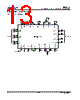
️· What it is: The MS6713 is a digital audio processor intended for controlling and managing audio output in a system (likely for speakers or audio zones).
️· Control: It allows for digital control over volume, speaker attenuation (on/off/level), audio switching/routing, bass and treble adjustments, and overall mute functionality.
️· Communication: It communicates over an I2C (Inter-Integrated Circuit) serial bus. This means a microcontroller or other digital logic can send commands and data to the MS6713.
2. I2C Communication
️· Address: The I2C chip address is `88h` (hexadecimal).
️· Write/Read: The 8th bit of the address byte determines read/write mode:
- `0`: Write operation (sending commands/data *to* the MS6713).
- `1`: Read operation (reading data *from* the MS6713 - functionality isn't detailed).
️· Acknowledge: The MS6713 is expected to acknowledge the end of each transmitted byte during a write operation.
️· Protocol:
- Start Condition
- Chip Address (including R/W bit)
- Data Byte(s)
- Acknowledge
- Stop Condition
3. Data Bytes and Control
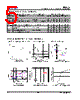
The following table summarizes the data bytes and their function. Each byte is comprised of 8 bits (MSB = Most Significant Bit, LSB = Least Significant Bit). The 'default' or initial state when power is applied is also noted.
| Function | MSB | Bit 3 | Bit 2 | Bit 1 | Bit 0 | A2 | A1 | A0 | Default |
|---|---|---|---|---|---|---|---|---|---|
| Volume Control | 0 | 0 | B2 | B1 | B0 | A2 | A1 | A0 | -78.75dB |
| -8.75dB Steps | |||||||||
| Speaker ATT LR | 1 | 0 | 0 | B1 | B0 | A2 | A1 | A0 | Mute |
| -8.75dB Steps | |||||||||
| Speaker ATT RR | 1 | 0 | 1 | B1 | B0 | A2 | A1 | A0 | Mute |
| Speaker ATT LF | 1 | 1 | 0 | B1 | B0 | A2 | A1 | A0 | Mute |
| Speaker ATT RF | 1 | 1 | 1 | B1 | B0 | A2 | A1 | A0 | Mute |
| Audio Switch | 0 | 1 | 0 | G1 | G0 | S2 | S1 | S0 | Default |
| Bass Control | 0 | 1 | 1 | 0 | C3 | C2 | C1 | C0 | Default |
| Treble Control | 0 | 1 | 1 | 1 | C3 | C2 | C1 | C0 | Default |
1. Overview & Function
️· What it is: The MS6713 is a digital audio processor intended for controlling and managing audio output in a system (likely for speakers or audio zones).
️· Control: It allows for digital control over volume, speaker attenuation (on/off/level), audio switching/routing, bass and treble adjustments, and overall mute functionality.
️· Communication: It communicates over an I2C (Inter-Integrated Circuit) serial bus. This means a microcontroller or other digital logic can send commands and data to the MS6713.
2. I2C Communication
️· Address: The I2C chip address is `88h` (hexadecimal).
️· Write/Read: The 8th bit of the address byte determines read/write mode:
- `0`: Write operation (sending commands/data *to* the MS6713).
- `1`: Read operation (reading data *from* the MS6713 - functionality isn't detailed).
️· Acknowledge: The MS6713 is expected to acknowledge the end of each transmitted byte during a write operation.
️· Protocol:
- Start Condition
- Chip Address (including R/W bit)
- Data Byte(s)
- Acknowledge
- Stop Condition
3. Data Bytes and Control
The following table summarizes the data bytes and their function. Each byte is comprised of 8 bits (MSB = Most Significant Bit, LSB = Least Significant Bit). The 'default' or initial state when power is applied is also noted.
| Function | MSB | Bit 3 | Bit 2 | Bit 1 | Bit 0 | A2 | A1 | A0 | Default |
|---|---|---|---|---|---|---|---|---|---|
| Volume Control | 0 | 0 | B2 | B1 | B0 | A2 | A1 | A0 | -78.75dB |
| -8.75dB Steps | |||||||||
| Speaker ATT LR | 1 | 0 | 0 | B1 | B0 | A2 | A1 | A0 | Mute |
| -8.75dB Steps | |||||||||
| Speaker ATT RR | 1 | 0 | 1 | B1 | B0 | A2 | A1 | A0 | Mute |
| Speaker ATT LF | 1 | 1 | 0 | B1 | B0 | A2 | A1 | A0 | Mute |
| Speaker ATT RF | 1 | 1 | 1 | B1 | B0 | A2 | A1 | A0 | Mute |
| Audio Switch | 0 | 1 | 0 | G1 | G0 | S2 | S1 | S0 | Default |
| Bass Control | 0 | 1 | 1 | 0 | C3 | C2 | C1 | C0 | Default |
| Treble Control | 0 | 1 | 1 | 1 | C3 | C2 | C1 | C0 | Default |
| Part No. | MS6713GU |
| Manufacturer | MOSA |
| Size | 608 Kbytes |
| Pages | 18 pages |
| Description | 3 Stereo Inputs and 4-Channel Outputs Volume, Tone, Balance, Fader, Loudness, and Selectable Input Gain |
| Вашему бизинису помогли Аллдатащит? [ DONATE ] |
Что такое Аллдатащит | реклама | контакт | Конфиденциальность | Ссылка на техническое описание | обмен ссыками | поиск по производителю All Rights Reserved©Alldatasheet.com |
| Russian : Alldatasheetru.com | Korean : Alldatasheet.co.kr | Spanish : Alldatasheet.es | French : Alldatasheet.fr | Italian : Alldatasheetit.com Portuguese : Alldatasheetpt.com | Polish : Alldatasheet.pl | Vietnamese : Alldatasheet.vn Indian : Alldatasheet.in | Mexican : Alldatasheet.com.mx | British : Alldatasheet.co.uk | New Zealand : Alldatasheet.co.nz |
|
Family Site : ic2ic.com |
icmetro.com |
 Russian ▼
  English
 Chinese
 German
 Japanese
 Korean
 Spanish
 French
 Italian
 Portuguese
 Polish
 Vietnamese
 Indian
 Mexican
 British
 New Zealand